Performance Calculator Abbreviation FSL A320
FSL A320 EFB requierd!
This document is only for the FSLabs A320 Family EFB Addon
Download PDFSection Overview
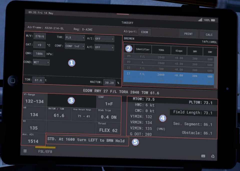
Section 1
TOW | Takeoff Weight Selected |
MACTOW | Mean average chord trim value in % |
Section 2
F/L | Full length |
TORA | Takeoff Run Distance Available |
SWY | Stopway (area beyond a runway which can be CWY = Clearway (area beyond a runway which is clear HWC = calculated Head Wind used for deceleration in case of a rejected takeoff) of obstacles and under airport authority control) Component (only 50% of that is taken as a positive value on the performance calculation). If a (-) value is shown it means tailwind is present and is calculated with a 150% penalty on perfomance. |
CWY | Clearway (area beyond a runway which is clear of obstacles and under airport authority control) |
Section 3
V1-Range | Upper and lower permissable V1 speed. The Stop Margin Range in meters will reflect the upper and lower V1 limit. In this example the V1 of 132 Kts corresponds to 71 m Stop Margin, while the V1 of 134 kts corresponds to a Stop Margin of 41 m. |
VR | Please see Section 4 |
V2 | Please see Section 4 |
Acc. Alt | Altitude where the aircraft is levelled off in case of an engine failure to start the acceleration phase (3rd segment). |
Section 4
MTOW | Maximum Takeoff Weight (certified maximum structual weight for Takeoff). |
PLTOW | Performance Limited Takeoff Weight (smallest and hence limiting value of the three cases Field Length Limit, Second Segment Limit or Obstable Limit) In this example the Field Length Limit is the value limiting the maximum takeoff weight. |
HWC | Weight (certified maximum structual weight for Takeoff) |
CWC | Calculated Cross Wind Component (as a general rule VMCG is derived during testing with a CWC of less than 5 kts. Hence with CWC between 5 and 15 kts the V1 should not be less than 120 kts and with a CWC > 15 kts the V1 should not be less than 130 [kts]). |
V1MIN | Minimum V1 speed due to VMCG (minimum control speed ground) which is the minimum speed, whilst on the ground, that directional control can be maintained by using only aerodynamic controls, with one engine inoperative (critical engine on two engine airplanes) and takeoff power applied on the other engine(s). |
VRMIN | Minimum VR (rotation) speed due to VMCA (minimum control speed air) which is the minimum speed, whilst on the ground, that directional control can be maintained, with one engine inoperative (critical engine on two engine airplanes) and takeoff power applied on the other engine(s) and a maximum of 5 degrees of bank towards the good engine(s). |
V2MIN | Minimum V2 (engine failure best angle of climb speed) limited to VMCA (minimum control speed air) or VMU (minimum Unstick Speed - which is the lowest speed where a liftoff is possible). In this example V2MIN is limited by VMU. |
Section 5
STD. At 1600 turn | Engine failure departure /climbout procedure. |